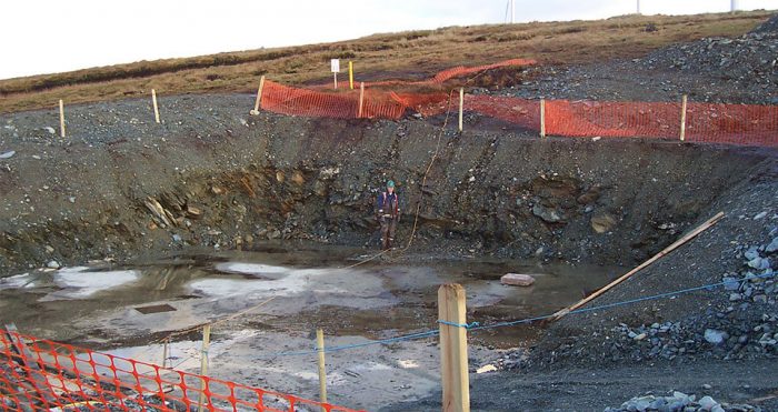
2D / 3D Resistivity (Electrical Resistivity Tomography)

Electrical Resistivity Tomography
Resistivity methods use small electrical currents that are flowing through the subsurface through small metal spikes called electrodes. Resistivity meters are measuring the electrical potential at other electrodes and determine the ground resistivity.
By using many electrodes along lines or grids the resistivity can be determined at several hundreds and up to many thousand locations in 2D or 3D arrangements within the ground. Key parameters like array type, electrode spacing and location, current injection and quality settings are optimized depending on the aims of the survey.
The resistivity is typical for the material in the ground: Clay has a low resistivity while sand and gravel have high resistivity, water saturated zones have a lower resistivity like dry zones, many rock types have high resistivity and sulphides, metal and ore bodies have low values.
2D-Resistivity is a widely used method that locates historic landfills, ground water bearing zones in rock and overburden, saline intrusions or tunnels and caves.
Such contrasts are used in the interpretation, and the better the contrast the better for the results. Data processing consists mainly of tomographic inversion methods that give 2D cross sections or 3D cubes of resistivity that is used as an image of the subsurface. Forward modelling can be carried out as an interactive process out to solve specific quests.
